
Thomas Tilley
[ Home ] [ Publications ] [ Resume ] [ Family ] [ Projects ] [ The Others ] [ Sitemap ]
[ Home ] [ Publications ] [ Resume ] [ Family ] [ Projects ] [ The Others ] [ Sitemap ]
 | |
 | |
 | |
 | |
 | |
 | |
 |
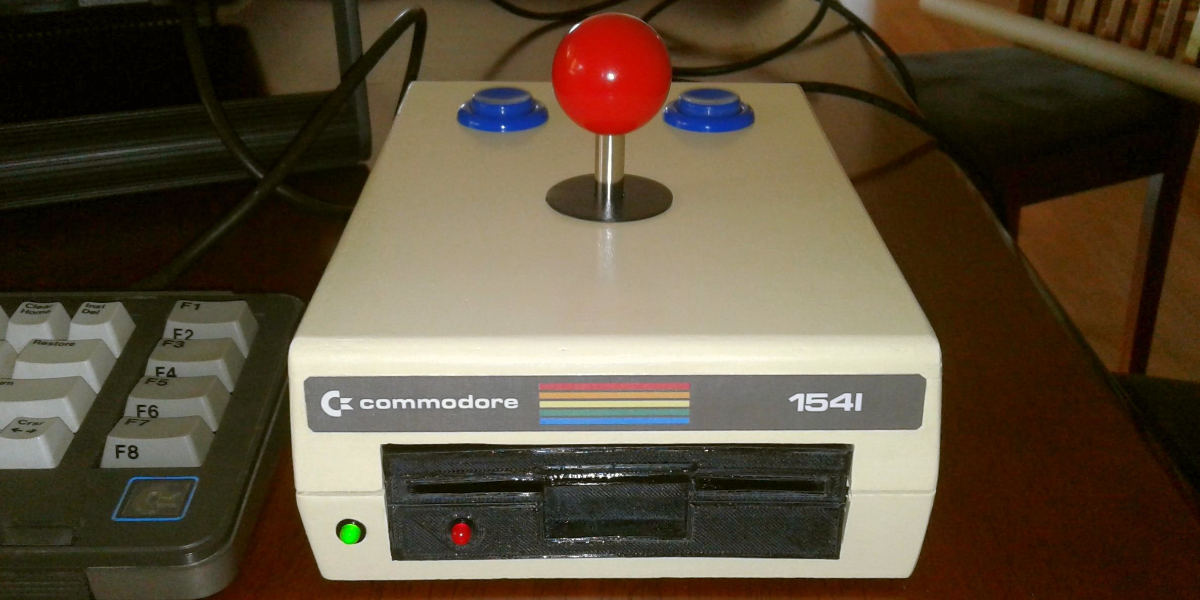
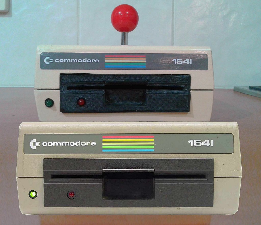
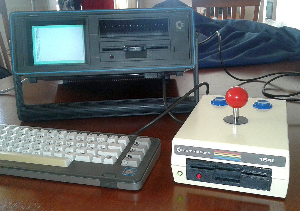
This is a custom Commodore 64 compatible joystick I built in a case that looks like the iconic Commodore 1541 disk drive. Note that it only looks like a disk drive - it's just a joystick and no actual 1541's were harmed during it's construction!
When I was invited to speak to the Adelaide Retro Computing Group I thought it would be fun to take along/lug my SX-64. I realised that I didn't have a compatible joystick anymore, so I decided to make one. However, rather than simply mounting an arcade joystick and button in a project case or re-purposed lunch box, I thought it would be fun to make it look like a smaller version of the Commodore 64's external disk drive with LEDs that light up when it's plugged in.
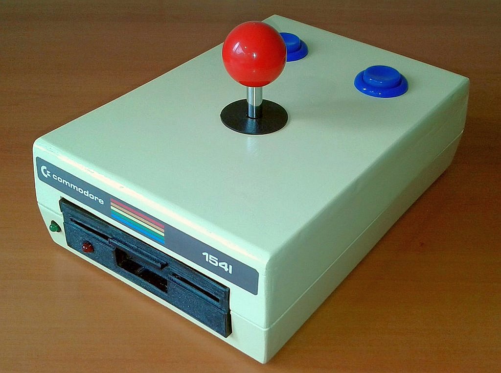
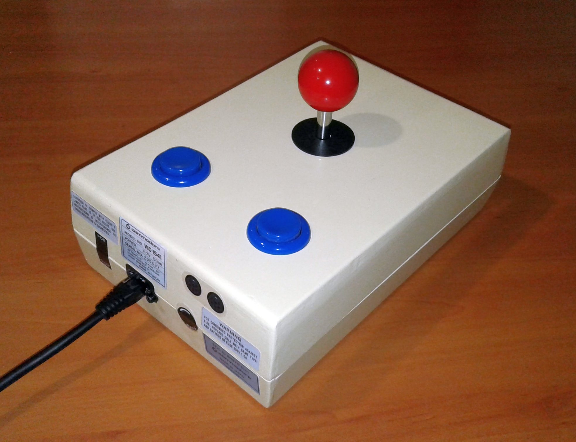
The Commodore 64's joysticks only support a single button but I included two so that it would be comfortable for both right and left-handed players. The case is just high enough to fit the buttons inside which is what determined the size.
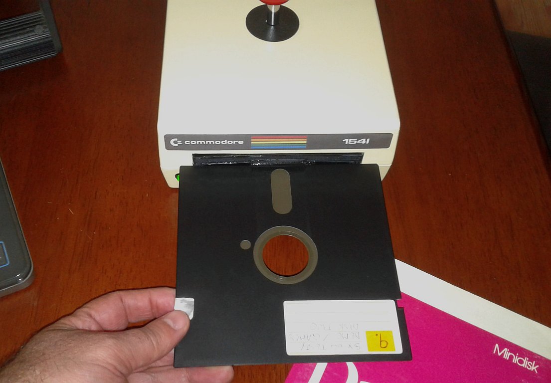
I didn't have a banana to use for scale but the 5 1/4" diskette in the picture below (if you still remember them!) will give you an idea of its size. The case is about 80% of the width and height of an actual 1541 (see the rightmost image comparing the two below) but only about 66% of its length (156mm Wide x 70mm High x 225mm Deep - approx. 6 9/64" x 2 3/4" x 8 55/64").
Read on below for details about how the joystick was made.
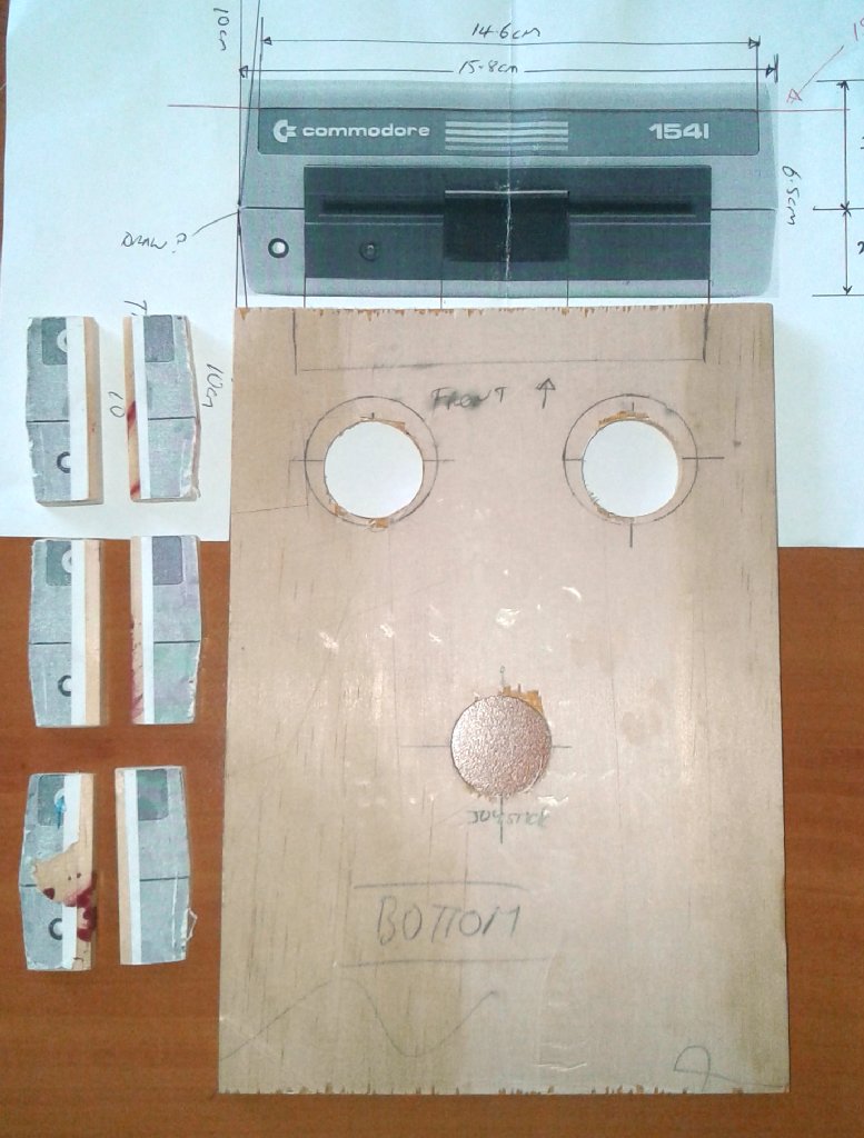
After a quick Google search for images of the 1541 I started by scaling a front view of the disk drive so that it was just high enough to accommodate the arcade buttons. The original plastic case of the 1541 has a distinctive and somewhat unusual look that I wanted to reproduce. It appears to be made of two sections with 4/7 on the top and 3/7 at the bottom with an obvious join betwen them that runs right around the outside of the case. The drive itself pokes out slightly through the front.
I printed out five copies of the image at the actual size I wanted and glued these onto some strips of 9mm (3/8") plywood. Using the images on the strips I could then cut them at the correct angles to make ten ribs that would give the desired shape to the four sides of the case. These were glued onto another piece of 9mm plywood that I used for the top of the case.
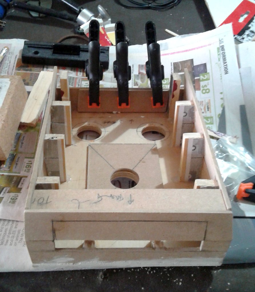
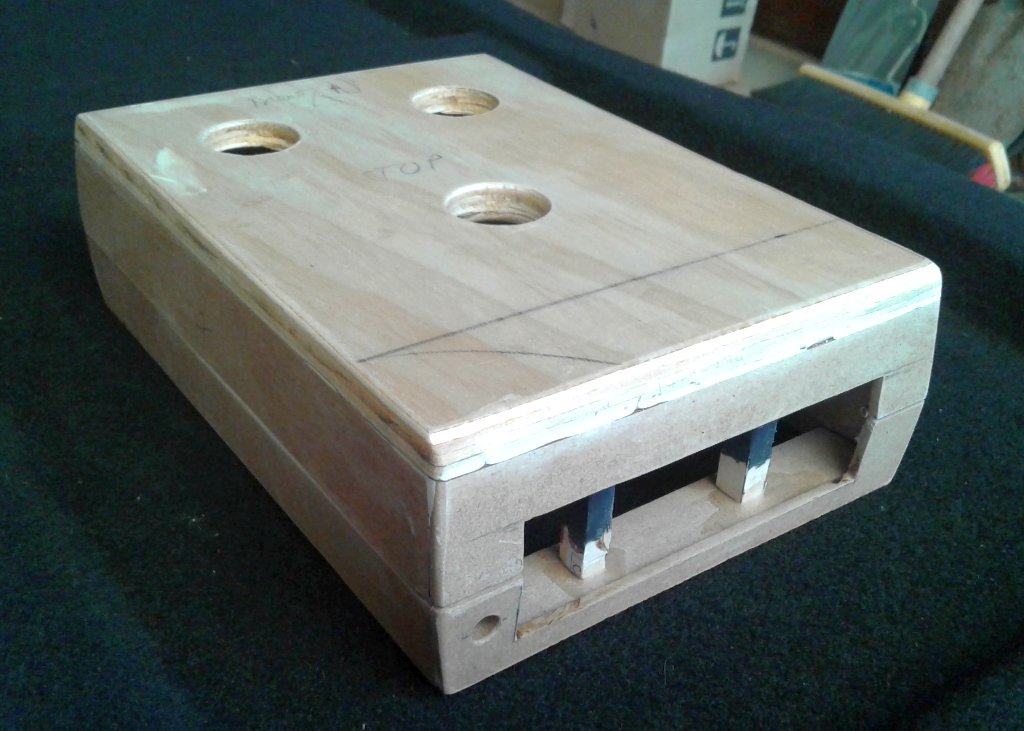
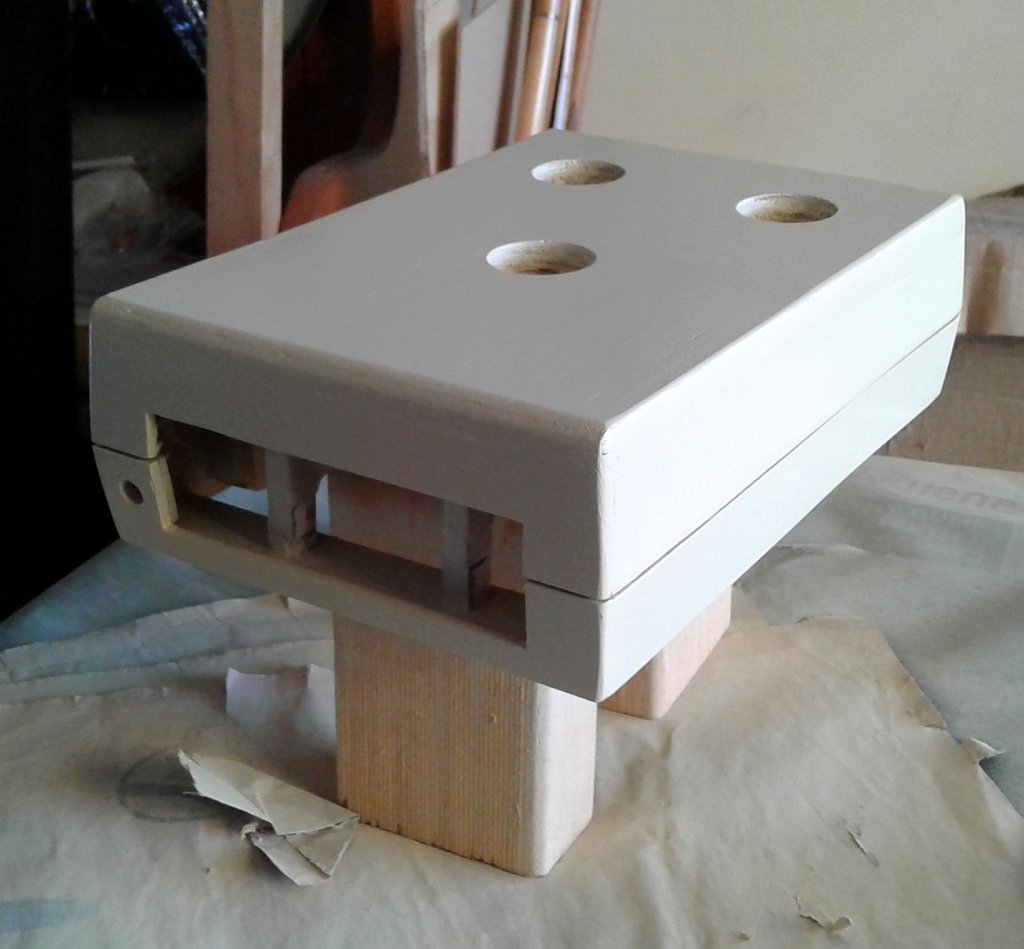
The sides are made from strips of 3mm (3/32") MDF and after a bit of putty and some sanding I was quite happy with the overall shape. I sealed the outside of the MDF using some slightly watered down PVA glue and then sprayed it with some "Bahama Beige" automative spray paint that a local automative-parts chain was selling for only $1 per can!
Facade
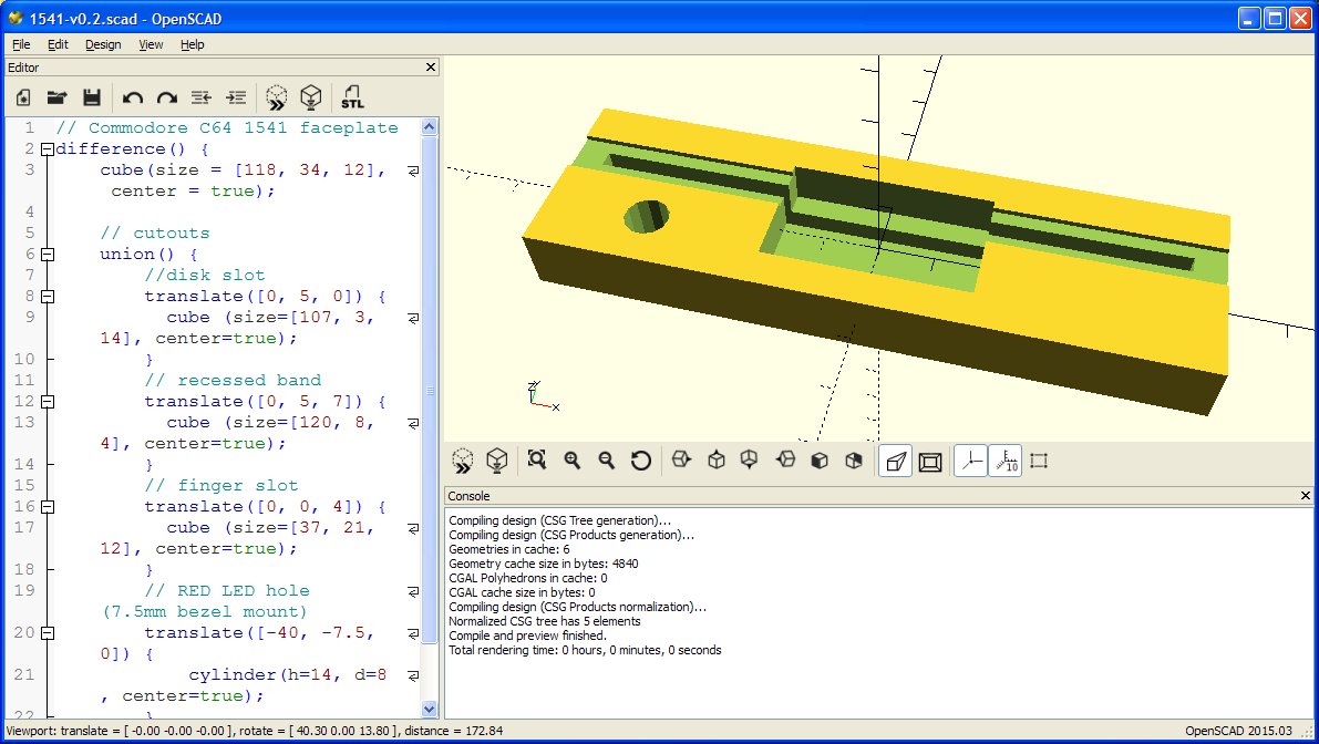
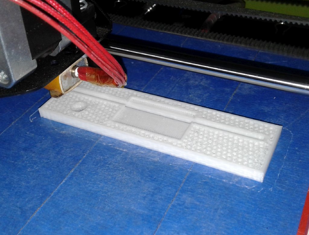
To get a mini 5 1/4" disk drive face I made a quick model in OpenSCAD that I then 3D printed and spray painted black. Unfortunately I blasted it with the hot air gun for just a little too long while trying to remove some strings of plastic and I warped it slightly but was still happy with the overall look.
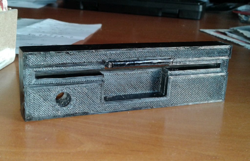
The "Commodore 1541" strip on the front and the details on the back were all just laser printed on paper, cut out, and attached with PVA glue. I recreated the graphics using images from the web as well as three of the stickers from Rockey Bergen's fantastic Commodore 1541 Disk Drive Papercraft.
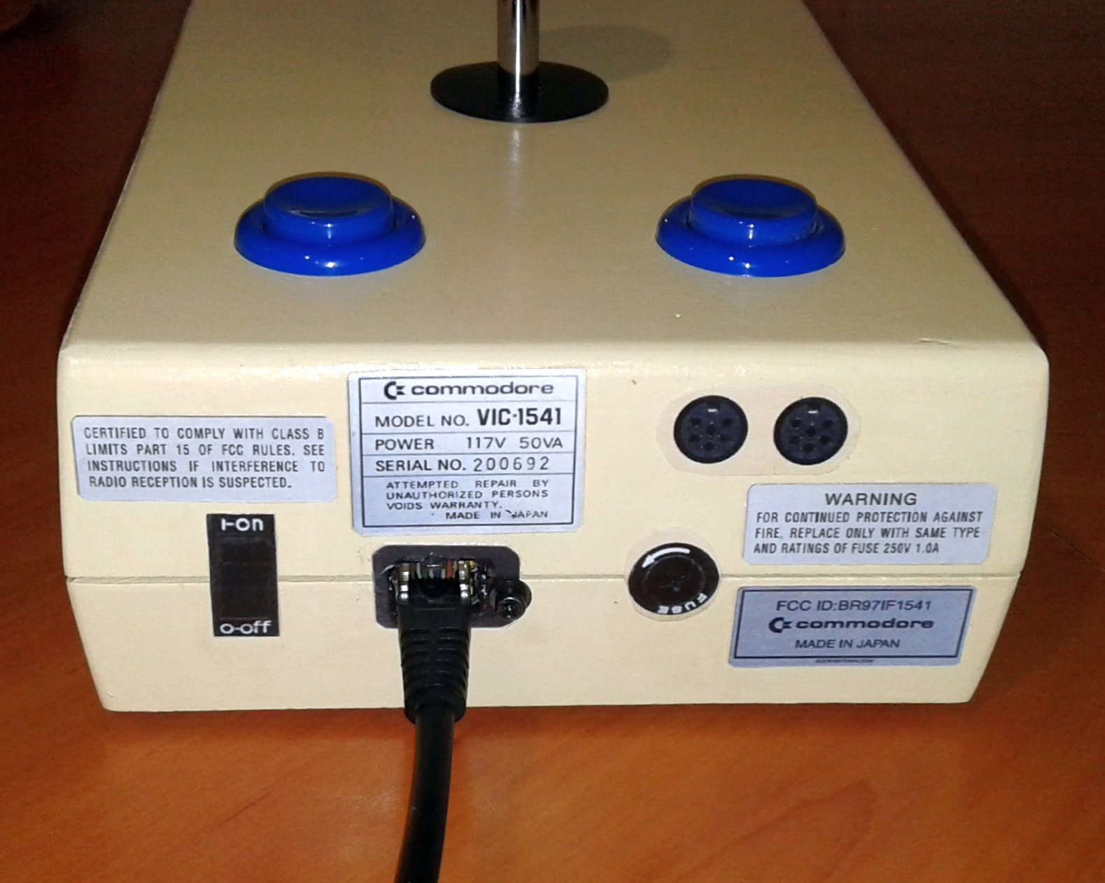
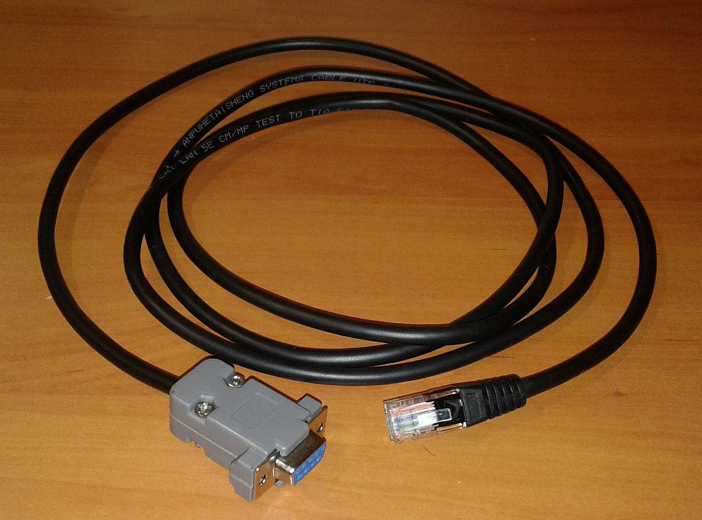
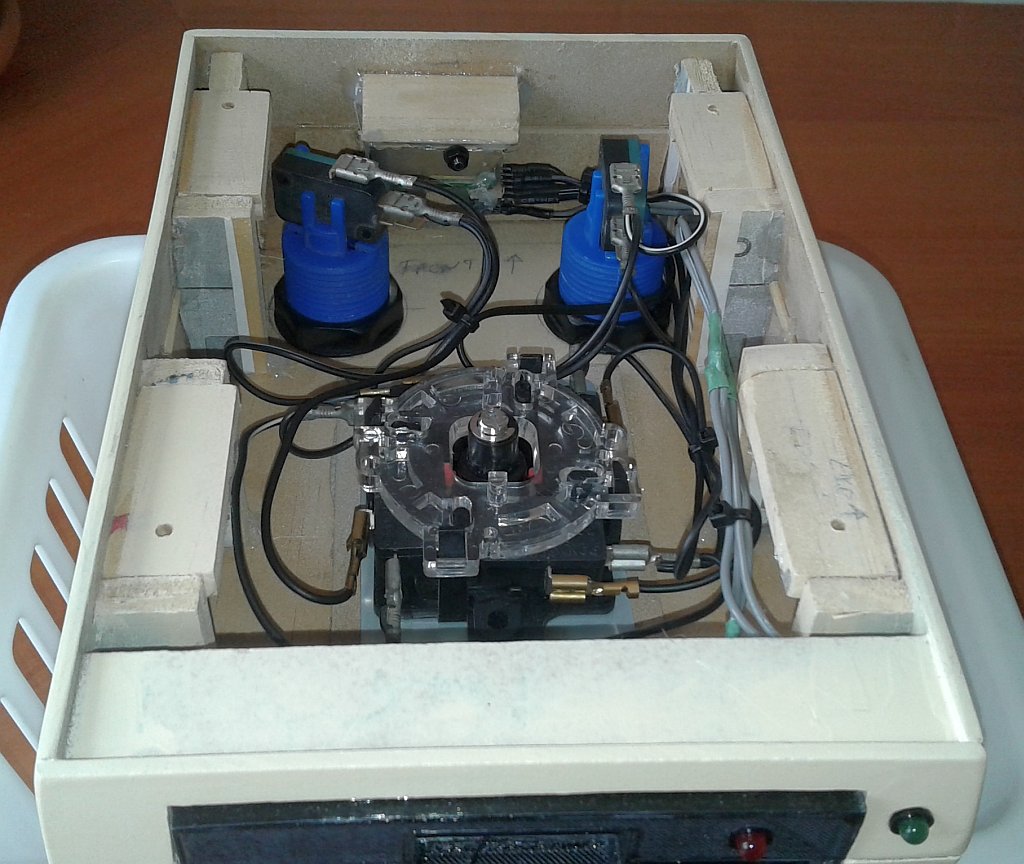
The Commodore 64's two control ports are 9-pin D-sub (DE-9) male connectors. After looking at the pinout I realised I would need to use 7 of these pins: Up, Down, Left, Right, Fire, and Ground, plus the 5V connection to power the two LEDs. In a local op shop I found a nice 1.5m long black network cable for $2. The cable had 8 wires and I simply cut off one of the RJ-45 connectors and soldered on a female DE-9 connector that was left over from some of my other projects.
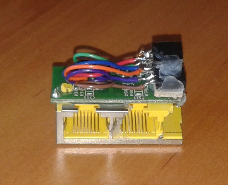
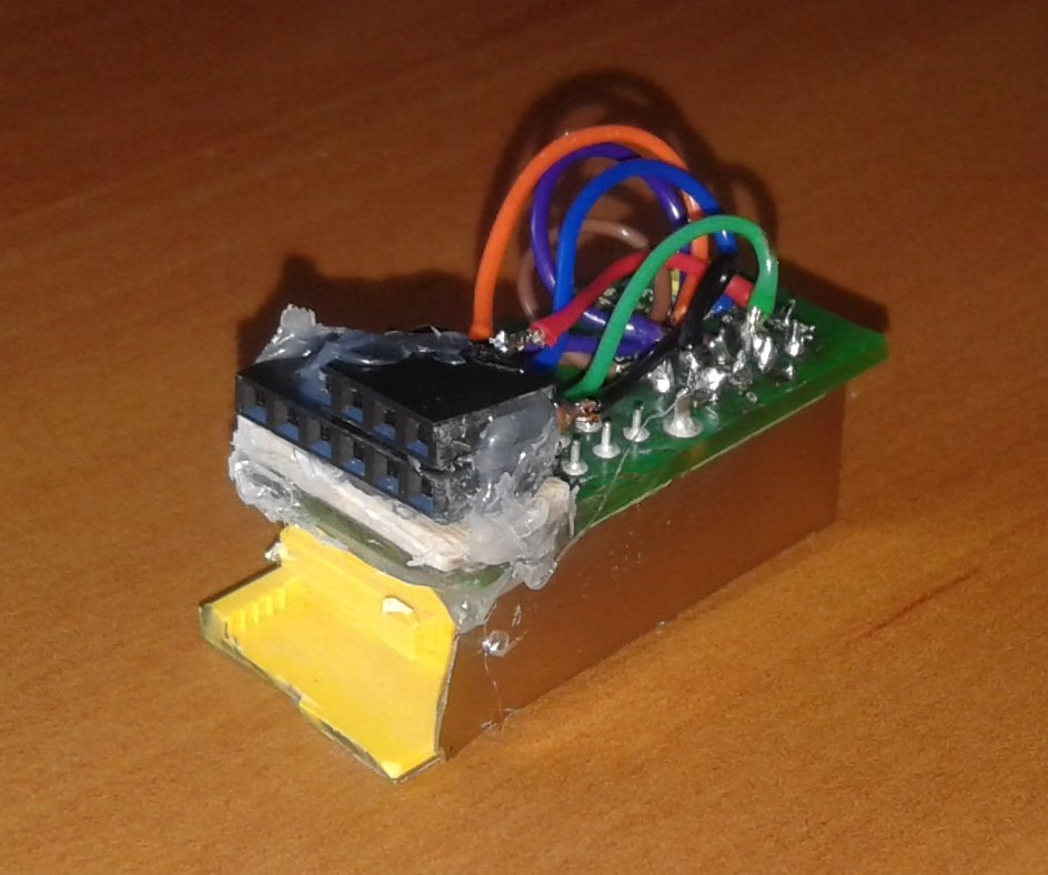
Using a Dremel I cut out half of a 4-port RJ-45 connector from the back of an old router. On top of this I hot-melt glued two strips of female header and carefully soldered wires to the pins on one of the RJ-45 sockets (see the middle images below). The top header strip was used to connect the +5V and Ground wires to the LEDs which were wired to male header pins with 150Ω 1/4W resistors in series.
The joystick and button switches were wired along with a common Ground connection to a 6-pin male header strip which plugged into the lower connector. I scavenged the spade connectors from the wiring harness of the voting machine I built for Payap's Got Talent back in 2009!
In the rightmost image below you can see the RJ-45 connector mounted at the back of the joystick and that the two arcade buttons just fit into the case.
Having wired it up I bravely plugged it into my treasued SX-64 for the first time and was pleased to see that both of the LEDs came on as expected. Using a single line of BASIC I was able to check that the joystick was working correctly and after swapping over the spade connectors on the joystick's left and right microswitches I now had a working Commodore 64 joystick! Game on!
You may also be interested in some of my other (often game related) projects: