Thomas Tilley
[ Home ] [ Publications ] [ Resume ] [ Family ] [ Projects ] [ The Others ] [ Sitemap ]
[ Home ] [ Publications ] [ Resume ] [ Family ] [ Projects ] [ The Others ] [ Sitemap ]
 | |
 | |
 | |
 | |
 | |
 | |
 |

Note: this version of the instructions for step 11 can be adapted to
any joystick but the images below and the wire/pin numbers are for the
blue thumbstick board from an 'OKER' brand clear-bodied joystick with
the number 'VNS706-3D REV1.0' printed on the board. Read on below if this is
the board from your joystick
or click here to go back to
the original version of step 11.
For this step you will need these parts & tools:
| Parts | Tools |
|---|---|
|
|
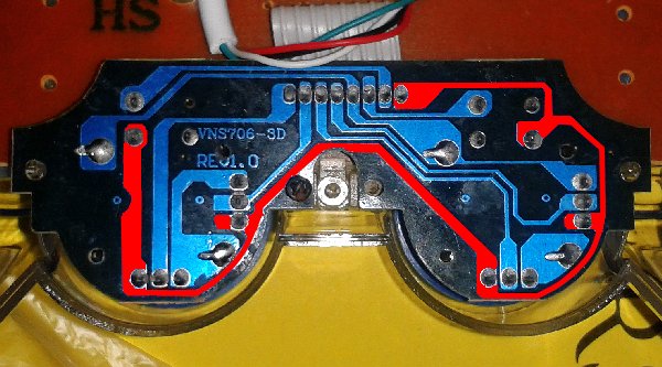
The brown component side of the thumbstick board contains two mini joysticks and looks the same in any Dualshock-like joystick. However, the layout of the circuit on the bottom of the board will vary from manufacturer to manufacturer. In this step we will look at the circuit to work out where to connect the four wires on the line sensor you made in the previous steps (the images used in this step are for an 'OKER' brand clear-bodied joystick with the number 'VNS706-3D REV1.0' printed on the thumbstick board but you can adapt the steps for any joystick.)
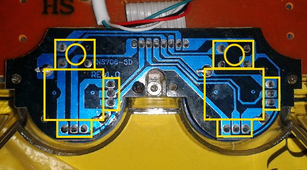
In the first image below I have overlaid the position of the two mini joysticks on the other side of the board in yellow. The small squares towards the top of the image are the buttons (you can click down on the thumbsticks) while the larger square shape is the body of the joystick. This is the bottom of the board so the sides are reversed - the right-side thumbstick is the one on the left and the left stick is the one overlaid on the right. The rectangles on the side of the mini-joysticks with three solder connections are the Y-axis variable resistors and the ones along the bottom are the X-axis resistors.
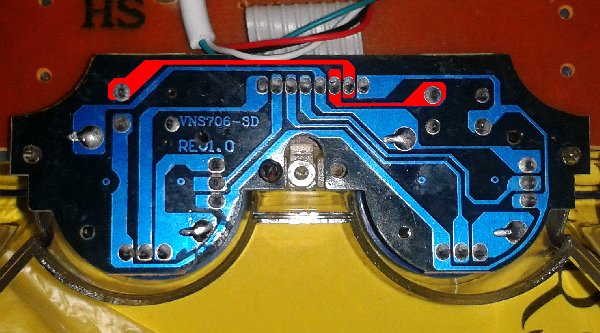
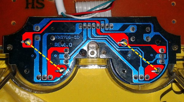
The ribbon cable that connects this board has eight wires: 2 for the buttons underneath the thumbsticks, 4 for the joystick axes (X and Y for each joystick), +5V, and ground. The 2 button wires are the easiest to identify and the wiring for these will simply run from one side of the cable connection to each of the buttons. They wiring won't be connected to any other components - just the buttons. See the right image below which has the button traces overlaid in red. If we number the 8 cable wires from left to right then the "left" button will be wire 6 and the "right" button wire 7.
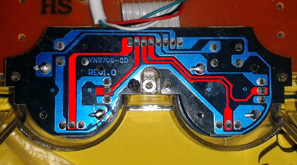
The wires for the joystick axes are also easy to identify because they are connected to the center pin of the joystick resistors. You can follow the wiring back from each of the resistors to the cable connection as shown in the image below left. On this board wires 1 and 2 are the Y-axis and X-axis for the right joystick and wires 3 and 4 are the Y-axis and X-axis for the left joystick respectively. See the image below left. So far you have identified 6 of the 8 wires - only 2 to go!
All of the components on this board (the four joystick variable resistors, and the two buttons) share one common connection and on USB joysticks this is normally connected to the +5V wire. An easy way to find this is to find a connection between one of the buttons and one of the variable resistors and follow it back to the cable connection on wire 8. The +5V wiring is shown in red in the left image below.
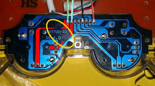
By a process of elimination that means wire 5 must be the ground connection because it is the only one left! This is easy to check because the ground connection is only connected to the variable resistors (and NOT the buttons). See the right image below. The only trick here is that sometimes the circuit designers use the metal body of the mini-joystick as a wire to connect parts of the circuit (overlaid dashed yellow lines). So while it looks like there are 3 separate red sections in this image they are all actually connected back to pin 5.
By just looking at the board you have been able to work out what the connections are but if you have a multimeter you can plug the joystick in carefully and check your +5V and ground wires. Choose a DC Voltage setting that is greater than 5V and connect the black lead to wire 5 (ground for this particular joystick board) and the red lead to wire 8 (+5V). Make sure you don't touch the leads together. If it doesn't read as around +5V then go back over the circuit again.
Now that you know which wires are which you can connect the line sensor. Use the side cutters to clip the ends of the wires down to around 4mm in length and then solder the sensor's:
See the picture below.
You now need to disconnect the joytick's resistors so that they don't interfere with the voltage dividers in the line detector. If you look carefully in the image below you will see inside the yellow oval that part of the right joystick wiring has been removed. Use the craft knife to carefully make two cuts about 2 or 3mm apart in the wiring to the X and Y joystick axes - you may need to choose a different location on your joystick. Heat the section in-between the cuts with a soldering iron for about 10 seconds and then you should be able to carefully remove it from the boards using the craft knife. If you have a multimeter you can check that this part of the circuit is now open so there is no connection between the joystick's resistors and your joystick axis wires.
Alternatively, you could carefully cut through the plastic along the sides of the two joystick axis wires on the connecting cable with the craft knife and then de-solder the connections from the board (by heating the connections on top of the board while pulling gently on the wires). You could then join your blue and green wires onto the newly de-soldered ends of the wire instead of modifying the board.
(Note that the picture of the thumbstick board that I've used in this step is still screwed into the joystick but your board will still be loose - for now.)